
How Is a Floating Solar System Designed for a 25-Year Service Life?
Introduction
A 25-year service life is common in the financial model of a photovoltaic project, but water changes the engineering challenge. A floating solar plant must operate while exposed to ultraviolet radiation, temperature cycles, wind, waves, currents, water-level variation, humidity, corrosion, abrasion, biofouling and repeated mechanical movement.
The lifetime is therefore not guaranteed by selecting a durable float or a photovoltaic module with a long warranty. It must be designed into the complete system: floats, structural connections, mooring lines, anchors, electrical cables, access systems, monitoring equipment and every interface between them.
This article explains how engineers translate a 25-year target into a design basis, material requirements, load calculations, qualification tests, inspection plans and replaceable components. It also explains why long service life is demonstrated through evidence and maintenance—not assumed from a single laboratory value.
A 25-year target is a system requirement
Service life is the period during which a system is expected to perform its intended function with acceptable safety, reliability and maintenance. It is not the same as a warranty period, and it does not mean that every component will remain untouched for 25 years.
Some components may be designed to last for the full project life. Others may have planned inspection, maintenance or replacement intervals. The design must identify which category each component belongs to, how deterioration will be detected and whether replacement can be completed safely without dismantling the entire plant.
A credible lifetime strategy connects five elements: the environment, the loads, material degradation, component resistance and the inspection-and-maintenance plan. If one element is missing, the 25-year claim is incomplete.
1. Establish a site-specific design basis
Long-term design begins with a documented design basis. It defines where the plant will operate, which environmental conditions it must withstand, how it will be used and what level of reliability is required.
The design basis should include normal operating conditions, recurring seasonal conditions, extreme events, accidental situations, construction and towing conditions, inspection assumptions and the intended service life.
Key site inputs
Wind speed, direction, turbulence and duration, including normal and extreme events.
Wave height, period, direction and number of cycles expected over the project life.
Currents, tides and changing water levels where relevant.
Air and water temperatures, thermal cycling, snow, ice and solar exposure.
Water chemistry, salinity, pollution, biological activity and corrosion environment.
Bathymetry, shoreline geometry and geotechnical conditions at anchor locations.
Navigation, debris, vessel interaction, maintenance access and credible accidental loads.
The environmental conditions must be combined with the array geometry and operational limits. A system designed for a small sheltered basin cannot automatically be transferred to a large reservoir or nearshore port simply because the installed capacity is similar.
2. Design for both extreme loads and fatigue
Extreme-load calculations check whether the plant can survive rare high-load events such as storms, maximum water levels or accidental line failure. Fatigue analysis addresses a different question: can the system tolerate millions of smaller load cycles accumulated over many years?
Floating solar structures move continuously. Waves flex connections, wind changes line tension, water-level variation changes mooring geometry and thermal cycles expand and contract materials. A component can remain far below its breaking load and still fail gradually through fatigue, wear, creep or stress concentration.
The analysis should consider the complete load path from the wind-loaded modules through supports, floats, connectors and mooring attachments to the lines and anchors. Local details often govern durability: holes, sharp corners, fastener interfaces, rope terminations and transitions between flexible and rigid elements.
Appropriate safety factors, realistic load combinations and fatigue resistance must be selected for the component, failure consequence and uncertainty in the data. Redundancy should be considered where one local failure could otherwise propagate through the array.
3. Account for long-term polymer behaviour
High-density polyethylene is widely used for floating structures because it combines buoyancy, impact resistance, processability and resistance to many water environments. Its long-term performance still depends on resin grade, stabilisation, pigment, processing quality, wall thickness, stress level and exposure.
Ultraviolet radiation and oxidation
Solar radiation can break polymer chains and progressively reduce ductility or impact resistance. UV stabilisers, antioxidants, appropriate pigments and sufficient material thickness help slow this process, but their performance must be supported by formulation control and ageing evidence.
Accelerated weathering can compare formulations and reveal degradation mechanisms, but exposure hours do not convert directly into years of field life without a justified correlation. Laboratory results should be combined with material data, outdoor exposure, mechanical testing and conservative engineering assumptions.
Creep and stress relaxation
Polymers deform over time under sustained load. This creep behaviour is strongly affected by temperature and stress. Connections, supports and float features should therefore be designed using long-term allowable stresses rather than short-term tensile strength alone.
Processing and manufacturing quality
A suitable resin can perform poorly if moulding or extrusion creates thin zones, residual stress, voids, poor fusion or inconsistent additive dispersion. Material traceability, controlled processing parameters, dimensional inspection and representative component testing are part of lifetime engineering.
4. Protect metallic components from corrosion
Metal brackets, bolts, shackles, chains, anchors and electrical enclosures may be exposed to water, condensation, splash, salts and dissimilar materials. Corrosion protection must match the environment and expected inspection access.
Material selection may involve stainless steels, galvanised or coated carbon steel, aluminium alloys or engineered combinations. The design must also consider galvanic corrosion between dissimilar metals, crevices that retain water, coating damage, fastener preload and wear at moving interfaces.
Nearshore and saline sites require a more demanding strategy than most freshwater reservoirs. Corrosion allowance, coatings, replaceable sacrificial elements, isolation between metals and inspection intervals should be defined rather than left to general statements such as marine grade.
5. Engineer connectors as fatigue-critical components
Connectors allow individual floats or structural modules to act as one array. They transfer wind and wave loads while accommodating movement. Over 25 years they may experience a very large number of load reversals, rotations and local contacts.
Connector design should evaluate ultimate strength, fatigue, stiffness, impact, wear, dimensional tolerances, installation error and the consequences of one connection becoming loose or damaged. The surrounding float geometry must distribute forces without creating local stress concentrations.
Full-scale testing is valuable because small details in geometry, assembly and friction are difficult to represent through material coupons alone. Testing should reproduce the relevant load direction, amplitude, frequency, temperature and wet conditions as closely as practical.
6. Design mooring and anchoring for changing conditions
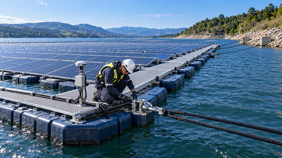
The station-keeping system must control the array throughout the complete water-level range and environmental envelope. Its lifetime depends on the interaction between lines, connectors, attachment points, anchors, bed conditions and the floating platform.
Mooring lines may be exposed to cyclic tension, creep, abrasion, ultraviolet radiation, marine growth, corrosion or contact with the bed. Terminations and shackles can experience higher local stresses than the line itself. Anchor capacity may also change if the bed erodes, sediment moves or installation does not achieve the assumed geometry.
The design should define acceptable movement, minimum and maximum line tension, fatigue utilisation, abrasion protection, redundancy and inspection access. As-built anchor positions, line lengths and pretension should be recorded so that later inspections can be compared with the installed condition.
Industry frameworks increasingly treat floats and station keeping as coordinated systems. DNV-RP-0584 covers the development and operation of floating PV systems, while the 2026 DNV standards DNV-ST-C108 and DNV-ST-E309 provide aligned requirements for structural float design and station keeping.
7. Protect electrical systems against water and movement
PV modules may be familiar components, but floating installations create demanding electrical interfaces. Cables move with the platform, connectors operate close to water and the route from the array to shore must accommodate waves and water-level change.
Cable design should address bending radius, cyclic motion, strain relief, buoyancy, abrasion, ultraviolet resistance, water exposure, connector location, fire behaviour and protection from maintenance activities. Cable loops should allow controlled movement without becoming snag points.
Junction boxes, inverters, transformers, monitoring devices and enclosures need suitable environmental protection and installation positions. Earthing, bonding, lightning protection, insulation monitoring and emergency isolation must be integrated into the overall electrical design.
Electrical components with shorter expected lives should be accessible and replaceable. A 25-year plant should not depend on an inverter, sensor or cable junction remaining maintenance-free for the full project period.
8. Qualify components and validate the assembled system
Material certificates are necessary, but they do not demonstrate the behaviour of the complete floating plant. Qualification should progress from material properties to components, connections, subassemblies and system-level performance.
A practical validation hierarchy
Material testing: tensile, impact, creep, environmental stress cracking, UV ageing, oxidation and relevant chemical resistance.
Component testing: buoyancy, leak tightness, dimensional stability, connection strength, fatigue, pull-out and local failure modes.
Subassembly testing: repeated movement, combined load directions, tolerances, cable routing and realistic installation details.
System analysis: global loads, hydrodynamic response, load distribution, station keeping and accidental cases.
Prototype or demonstrator monitoring: measured motions, loads, environmental conditions, energy performance and degradation observations.
Manufacturing quality control: traceability, process parameters, inspection records, acceptance criteria and nonconformity management.
Test conditions must be linked to the design basis. Passing a test is meaningful only when its loads, duration, specimen preparation and failure criteria represent the intended application.
9. Design for inspection, maintenance and replacement
Maintainability is one of the strongest predictors of real service life. A robust component can still become a project risk if it cannot be inspected or replaced safely.
The layout should provide access to critical connections, mooring points, electrical equipment and monitoring devices. Components that are expected to wear should be replaceable using realistic tools, personnel and weather windows. Spare-parts availability and compatibility should be considered during procurement.
The O&M plan should define routine visual checks, periodic detailed inspections and event-driven inspections after storms, abnormal movement, electrical faults or impact. Acceptance limits should state when a component can remain in service, requires closer monitoring or must be replaced.
10. Use monitoring to verify design assumptions
Monitoring turns a lifetime prediction into an evidence-based operating process. Environmental and structural data can show whether the real site is behaving within the design envelope and whether loads or movements are changing.
Depending on the project, useful measurements may include wind, waves, water level, air and water temperature, array inclination, position, mooring-line tension, connector movement, electrical output, insulation alarms and camera observations.
The objective is not to collect data without limits. Each measurement should support a decision: confirm a design assumption, detect degradation, trigger inspection, diagnose underperformance or improve future designs. Alarm thresholds and responsibilities for reviewing data should be defined before operation begins.
11. Control documentation throughout the project life
Lifetime engineering depends on traceability. The owner should retain the design basis, calculations, drawings, material specifications, manufacturing records, test reports, installation records, anchor coordinates, line pretension, commissioning results and inspection history.
Repairs and replacements must be recorded. A substitute component with the same dimensions may have different stiffness, UV stability, corrosion resistance or fatigue behaviour. Change control prevents undocumented substitutions from weakening the original design.
At the end of the service period, complete records also support life extension, repowering or decommissioning decisions.
Inland and nearshore systems require different evidence
A sheltered inland reservoir and a nearshore port may share the same design logic, but not the same severity. Inland systems are often governed by wind, fetch-limited waves, water-level variation, snow or ice and reservoir operations.
Nearshore systems can add stronger waves, tides, currents, salinity, corrosion, biofouling, debris, vessel interaction and restricted marine access. These conditions increase the importance of hydrodynamic analysis, fatigue, corrosion protection, redundant station keeping and specialised inspection.
A 25-year claim should therefore be attached to a defined site class and design basis. Qualification for one environment should not be presented as universal proof for every water body.
A 25-year service-life checklist
Is the service-life target written into the design basis and assigned to every system and component?
Are normal, extreme, fatigue and accidental load cases defined for the actual site?
Are long-term polymer properties, UV stabilisation, creep and processing quality verified?
Are corrosion, galvanic interaction, abrasion and biofouling addressed for the water environment?
Are connector and mooring fatigue evaluated, including terminations and attachment points?
Are electrical cables and interfaces designed for repeated movement and water exposure?
Do qualification tests represent the real materials, geometry, manufacturing process and load path?
Can critical components be inspected and replaced safely during operation?
Are monitoring data linked to thresholds, inspections and maintenance decisions?
Are as-built records, material batches, tests, repairs and substitutions fully traceable?
Is the design periodically reviewed against operating experience and changes in site conditions?
Is there a plan for life extension, repowering and end-of-life removal?
FAQs
Does a 25-year design life mean no components will be replaced?
No. Some components may be designed for the full project life, while others require planned maintenance or replacement. The system should identify those components and make them accessible without compromising safety or production unnecessarily.
Can accelerated UV testing prove 25 years of outdoor life?
Accelerated testing can compare materials and reveal degradation, but exposure hours do not automatically equal a specific number of field years. A lifetime assessment should combine appropriate ageing tests, mechanical retention, formulation control, field data and justified environmental correlation.
Why is fatigue important for floating solar?
Floating structures experience repeated motion from waves, wind and water-level changes. Millions of moderate cycles can damage connectors, mooring lines, fasteners and cable interfaces even when no single event approaches the breaking load.
Which components are most critical for long-term reliability?
Critical components vary by design, but load-transfer connections, mooring attachments, lines and anchors, dynamic cable sections, water-to-shore transitions and inaccessible interfaces usually deserve particular attention.
How often should a floating solar plant be inspected?
Inspection frequency should be risk-based and site-specific. It normally combines routine visual checks, scheduled detailed inspections and additional inspections after severe weather, abnormal movement, impact or monitoring alarms.
Can an inland floating solar design be used nearshore?
The concept may provide a starting point, but the design basis must be recalculated. Nearshore conditions can add waves, tides, currents, salinity, corrosion, biofouling and more difficult maintenance access.
How can project owners verify a 25-year claim?
Ask for the design basis, material and component qualification evidence, structural and fatigue calculations, manufacturing controls, system test results, inspection strategy, replaceability plan, monitoring approach and operating data from representative environments.
Conclusion
A 25-year floating solar service life is not created by one strong component or one accelerated-ageing test. It results from a traceable engineering process that connects the site environment to loads, material degradation, structural resistance, testing, quality control and operation.
The most reliable systems anticipate that materials age, components move and some parts will require intervention. They distribute loads clearly, protect vulnerable interfaces, allow inspection and replacement, and use monitoring to confirm that the asset remains within its design envelope.
HelioRec develops floating solar solutions for inland and nearshore environments using site-specific engineering, system-level load paths and monitored validation. Contact our team to discuss the design basis and lifetime strategy for your project.


